- Highlights of v1 and v2 Networks
- Networks After January 18, 2024
- Machines on v2 Networks
- Devices of a Machine on a v2 Network
- Remote Service Sessions after January 18, 2024
- Examples – How To Do Common Changes
Version 2 of ei3’s Argo network system greatly broadens the flexibility for ei3 administrators to set up new installations and improves the useability of ei3 SERVICE for its users. This system is called simply version 2 or “v2”, and it will be used for all networks created in SERVICE after January 2024. All existing network installations created prior to this date will be referred to as version 1 or “v1”, and they will continue to be supported.
Highlights of v1 and v2 Networks
v1 networks, standard ei3 configuration:
- Limit of seven red boxes per green box.
- Block of 256 IP Addresses required for the Shop Floor LAN.
- Limit of the number of devices on a red box is limited based on the Amphion Type (D, E, F, G).
- Remote connection via the Argo IP Address only prior to Jan 2024. After this, either Argo IP Address or device’s local IP Address may be used.
- Data exchanged between the red and green boxes are unencrypted, for easy inspection by local IT.
- Red and green boxes on the same physical LAN.
v2 networks, standard ei3 configuration:
- Up to 99 red boxes per green box.
- Only one IP address per red box is required for the Shop Floor LAN.
- Unlimited number of devices on a red box.
- Remote connection via the Argo IP Address or the device local IP Address.
- Option to encrypt data exchanged between the red and green boxes.
- Option to have red and green boxes on different physical LANs.
Keep reading to learn about more new features of the v2 networks.
Networks after January 18, 2024
Network Creation
All newly created networks after this date will be v2 networks. The user interface for ei3 SERVICE admins and users will essentially remain the same and no additional information needs to be entered when creating networks. Networks will be identified by the version number listed on the network page.
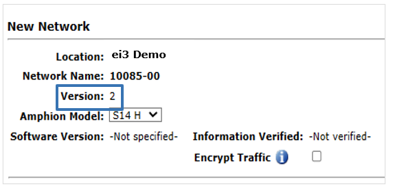
Default Shop Floor LAN Network Definition, Used for the Amphion Green Box Configuration
The standard default Shop Floor LAN subnet definition that is auto-populated when creating a new network is the same for v1 and v2 networks. The subnet definition can be changed to suit the requirements of the installation.
NOTE: It is recommended that at a minimum, sufficient IP space be provided for any additional devices needed for the physical network, any other internal factory network and technician needs for access or inclusion in the Shop Floor LAN, and further addition of more machines later.
Encrypting Data on the Shop Floor LAN
The option to encrypt data traffic between the green box and its connected red boxes is available on a v2 network. To use this option, check the box provided on the Edit Network page. After the network is saved with this option checked, each Amphion must be reconfigured to enable encryption between them.
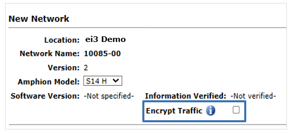
Note that a v1 network does not have this option, and hence must be converted to a v2 network to allow for data encryption in the Shop Floor LAN.
Network Conversion and Administration
Existing eligible v1 networks can be converted to a v2 network via the v1 Network Conversion tool on the Network Tools page, available via the Network Tools icon ![]() on the admin Edit Network page. The conversion will include all machines and devices defined in ei3 for the network. The conversion tool will not appear on the Network Tools page for v2 networks.
on the admin Edit Network page. The conversion will include all machines and devices defined in ei3 for the network. The conversion tool will not appear on the Network Tools page for v2 networks.
 WARNING: The existing v1 network will be disconnected from the ei3 private cloud by this process, and all Amphions on the network must be reconfigured with new configuration files using a USB stick for them to be brought back online with the v2 network. As an additional prerequisite, data collection must be stopped on all connected machines.
Administration of existing v1 networks remains the same, e.g. new machines and devices can be added to existing v1 networks under the same conditions existing prior to v2.
Machines on v2 Networks
Machine Creation
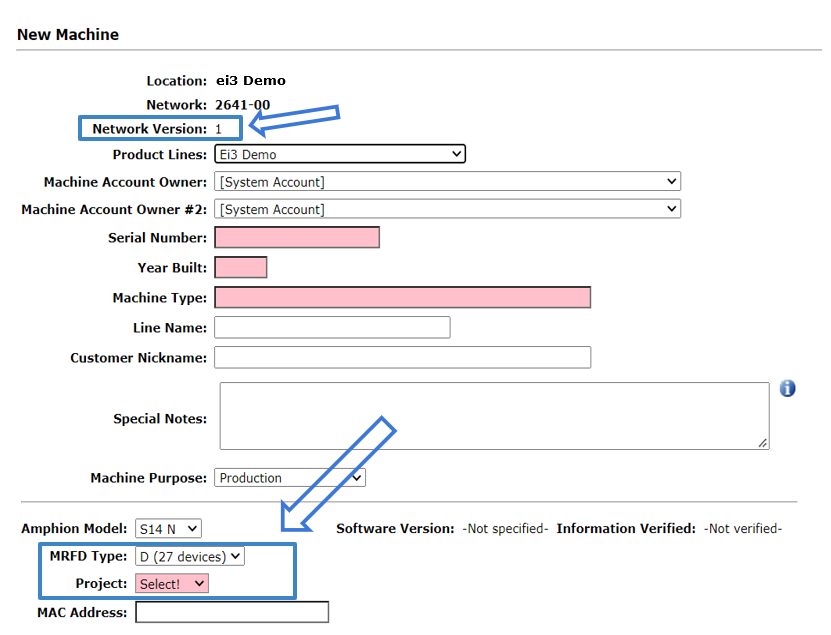
The machine creation process has been simplified for v2 machines. Project numbers are automatically assigned sequentially up to 99, so there is no longer a drop-down menu item for admin users to select the next available project number.
The image below shows what the New Machine page looked like for v1 machines. As you can see, you must select the Project number, which would be the next available one.
This next image shows a v2 machine, and as you can see, you no longer have to select the Project number as it is automatically assigned for you.
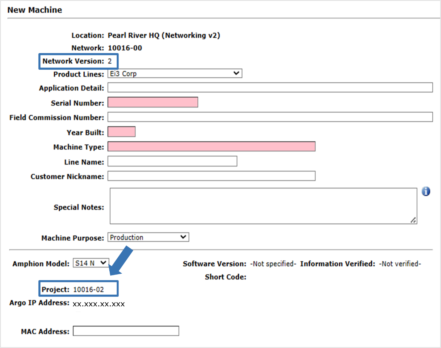
In addition, machines on v2 networks no longer use the MRFD Type required for machines in v1 networks to define the subnet block they use, because they use only one IP Address and are allowed an unlimited number of devices. Hence, the MRFD Type is not displayed for a machine on a v2 network as it is for a machine on a v1 network.
The network version used by the machine will be identified on the New Machine and Edit Machine pages, as seen below.

Single IP Address for the Red Box
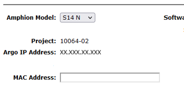
v2 machines only need a single IP Address for the Red Box. The Argo IP Address of the red box’s “To ei3” interface is displayed below the Project number and can be used to access the web User Interface of the Amphion.
Shop Floor LAN Definition for the Amphion Red Boxes
Within the LAN section of the Edit Machine page (Admin > Machine > ![]() ), there is a dropdown with Clear/Custom and Default.
), there is a dropdown with Clear/Custom and Default.

Selecting Default will auto-fill the Shop Floor LAN entry to align with the Shop Floor LAN that was previously defined for the Network. This is the proper selection for cases in which v2 network Amphions are on the same physical LAN.
The default network subnet information that appears is the same as the green box Amphion. Normally this information should not be changed. Red boxes on a v1 network have to be on the same physical LAN as their green box, so there isn’t an option to change a Shop Floor LAN for red boxes on v1 networks.
One reason to change the Shop Floor LAN definition would be when the red boxes are on a different physical LAN than the green box – this is described below. Another reason could be to manage an IP Address conflict with other, non-Amphion devices on the Shop Floor LAN.
Shop Floor LAN: Red and Green Boxes on Different Physical LANs
Selecting Custom/Clear from the dropdown shown in the previous image will allow the admin user to enter a custom IP Address, Gateway, and Subnet Mask for the Shop Floor LAN. This selection is primarily for defining the Shop Floor LAN interface differently between red boxes and green boxes to account for different physical networks.
The option to change the Shop Floor LAN information for a red box on v2 networks is available for more complex customer network configurations. One such configuration provides for red boxes to be on a different physical LAN than the green box to which they are connected. To accomplish this, the local network IT professionals must provide for routing between the two physical networks. The gateway of the machine red box must be configured such that it reaches the router, and all traffic must be allowed between the red boxes and their green box.
The Edit Network page contains a setting complimentary to the one described above. If the user checks the Advanced box on the Networks page, they can configure a gateway for the green box that will route traffic from the green network to the LANs defined in the Edit Machines page. This option is particularly useful in environments where more sophisticated routing setups are required. By defining a custom gateway, traffic originating from machines on the green network can be directed appropriately to different segments of the LAN, enabling communication across physically separated networks while ensuring proper integration between the green box and its associated red boxes.
Devices of a Machine on a v2 Network
Device Creation
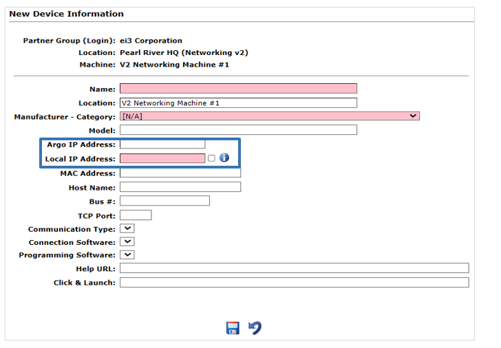
The user interface for creating devices is the same for machines on v1 and v2 networks. The required entries are Device Name, Manufacturer-Category, and Local IP Address. The Argo IP will be automatically assigned as the devices are created. There is no limit to the number of devices that can be created for a v2 machine.
Argo IP Assignment
The Argo IP Address for a device created on a machine in a v2 network is assigned at the time the device is created. As a result, the IP Addresses of subsequent devices added to a machine may not be sequential in numerical order with previous devices on the machine and there may be gaps in the address space depending upon when the device is created.
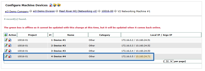
It is also important to note that when the Local IP of a device is modified, ei3 may generate a new Argo IP for the device in question.
Remote Service Sessions after January 18, 2024
The remote service process for machines using v1 and v2 networks is identical, and there are no significant changes in the SERVICE user interface. However, from this date onward SERVICE users can access the target machine devices using either the device’s local IP Address or its Argo IP Address. For more information see During a SERVICE Session – ei3 Knowledge Database
Examples for How To Do Common Changes
- In the case that a v1 network already has 7 machines but you would like to add more, you must convert this entire v1 network to a v2 network.
- Similarly, in a v1 network if you want to add more devices to a machine than the existing subnet definition allows for the red box for that machine, as identified by its MRFD Type, then you must convert the entire v1 network to a v2 network to remove the restriction for all machines on the network. This is accomplished by clicking on the Network Tools icon
 and selecting Convert a v1 Network to a v2 Network as described in the Network Conversion and Administration section above.
 - You can move individual machines from one network to a different network via the Move Machine function
 on the Edit Machine page, under certain conditions. You can also move a machine from a v1 to a v2 network and vice versa, under certain additional conditions as follows. Any machine move whether within v1 or v2 or across network versions must be completed with reconfiguration of the relevant red box Amphion with new configuration files. For more information see “How to Move Machines from One Network to Another”.
 - Machines on v1 networks can be moved to a v2 network as long as the v2 network has less than 99 machines already on it.
- Machines on v2 networks can be moved to a v1 network as long as the v1 network has an eligible subnet slot available as identified by project numbers on the network, since v1 networks can hold only 7 machines.
- When you import a machine from a v1 network into a v2 network, it will create a machine configured for the target v2 network. Importing a v2 machine template into a v1 network will create a v1 machine. For more information on how to import machines, view this article: “How to Create Machines Using a Template.”

