- Introduction
- Hardware Requirements
- Configuration in ei3
Introduction
The data collection method described in this article allows the Amphion to read data from Controls that support the Modbus protocol.
Modbus or MODBUS is a client/server data communications protocol in the application layer. It was originally published by Modicon (now Schneider Electric) in 1979 for use with its Programmable Logic Controllers (PLCs).
The Modbus protocol uses serial communication lines, Ethernet, or the Internet protocol suite as a transport layer. Modbus supports communication to and from multiple devices connected to the same cable or Ethernet network.
Hardware Requirements
The Modbus protocol is open-source and available on many different platforms and devices. All that is required for ei³ to collect data is support for Modbus in the PLC over Ethernet connection.
Configuration in ei3
Creating Modbus Devices in ei3
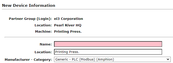
To configure a Modbus device in ei3, the following settings must be entered on the Edit Device page in the Customer Portal:
- Select the following Manufacturer – Category (also known as the device type): Generic – PLC (Modbus) (Amphion);
- Set the Local IP Address to the IP of the Modbus device;
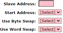
- Set the Slave Address, Start Address, Byte Swap, and Word Swap settings for the device. These settings can be tested with 3rd-party Modbus Client applications to confirm their correctness.
- Set the Modbus device port; normally this is set to 502.
Configuring Data Points
In ei3, it is not possible to access Modbus variables using tags or other names (or any other meaningful id/key) used in PLC programs or memory. Only absolute read addresses are supported in ei3.
- If the data point’s absolute read address is in the range of 30,000 – 39,999 then it is considered to lie within the Input Register.
To reference an Input Register variable in ei3 you must subtract 30,000 from the address and prefix the result with IR. For example, 30001 becomes IR1, and 30336 becomes IR336. - If the data point’s absolute read address is in the range of 40,000 – 49,999 then it is considered to lie within the Holding Register.
To reference a Holding Register variable in ei3 you must subtract 40,000 from the address and prefix the result with HR. For example, 40012 becomes IR12, and 41389 becomes HR1389.
Data Points Example
The machine operator or manufacturer might provide a list of tags similar to the following:
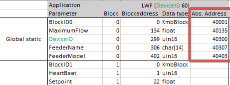
In this example, the absolute addresses of the variables are located in the right-most column. In ei3, they would have to be entered as follows:
- BlockID0 at absolute address 40001 becomes HR1 in ei3.
- MaximumFlow at 40135 becomes HR135.
- DeviceID at 40300 becomes HR300.
- …and so on.
