Introduction
The data collection method described in this article allows for the Amphion to read data from CAMAC 486/XTL/VEL Controls.
CAMAC Controls can be interfaced with another host using the RS-485 serial communication protocol if an FMC board is plugged into the control board. Then, as we do with the serial components, we can use a MOXA serial-to-ethernet device as a host; MOXA is then set up in the machine LAN in ei3.
Hardware Requirements
Daughter Board
- CAMAC 486 needs an FMC Board to accept host communication over RS-485. The FMC board has a lot of (4 or more) serial ports, use the first one by default.
- CAMAC XTL needs a Digi Board to accept host communication over RS-485.
- CAMAC VEL does not need a daughter board.
Serial Cable
- RS-485 (full duplex) cable (25-pin D following page VIII-42 of the spec to standard 9-pin D)
- Serial cable plugged into FMC board (DB-25 / 25-pin D)
- Serial cable plugged into Moxa Nport 5130 (DB-9 / 9-pin D)
Wiring Diagram
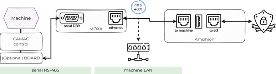
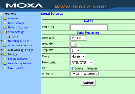
MOXA Setup
Serial Port Configuration
Ethernet Port Configuration

Configuration in ei3
Creating CAMAC Devices in ei3
To configure a CAMAC device in ei3, the following settings must be entered on the Edit Device page in the Customer Portal:
- Select the following Manufacturer – Category (also known as the device type): Milacron – CAMAC (Amphion);
- Set the Local IP Address to the IP of the MOXA device;
- Set the RS485 address; normally this is set to 1;
- Set the MOXA TCP port; normally this is set to 4001.

Configuring Data Points
To read a given point using scatter read, ei3 uses the RW_CONV_VEC (unsigned int 16 bits) read addresses. For example, to read Cycle Count, the read address will be 1221.
All the points are numeric values (unsigned int 16 bits) and usually require scaling to convert them to engineering units; see control documentation. Typical scaling requires the use of slope and offset; in ei3, a scaled equation needs to be put in place for the data points in question. The required scale equation is usually: “value_scaled = (value_raw – offset) * slope”.
If a single bit is extracted, it can be converted to a boolean (on / off) value, for example Machine Status (address 1160) contains 13 different on / off values represented by individual bits.
Examples:
- Numeric values: the read address 1161 will read Cycle Time (1161);
- Boolean values: the read address 1160.3 will read the running bit (bit 3) of the Machine Status (1160).
