- Verifying Data Points in UA Expert
- Setting The Device Manufacturer – Category
- Adding Data Points in ei3
- Starting Data Collection
Verifying Data Points in UA Expert
When you have an OPC UA-enabled device that you would like to connect to ei3 and collect data from, we recommend to use the software called UA Expert to verify what data is shared on the device and what are the exact read addresses for data points of interest.
Connecting to Devices
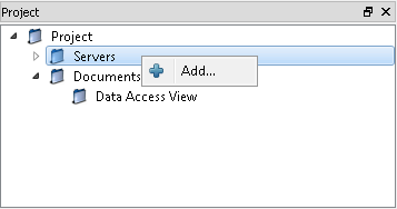
To connect to an OPC UA device using UA Expert, start by opening a remote session to the machine. Then, run the software, right-click Servers, and click Add:
Under Custom Discovery, double-click Add Server:
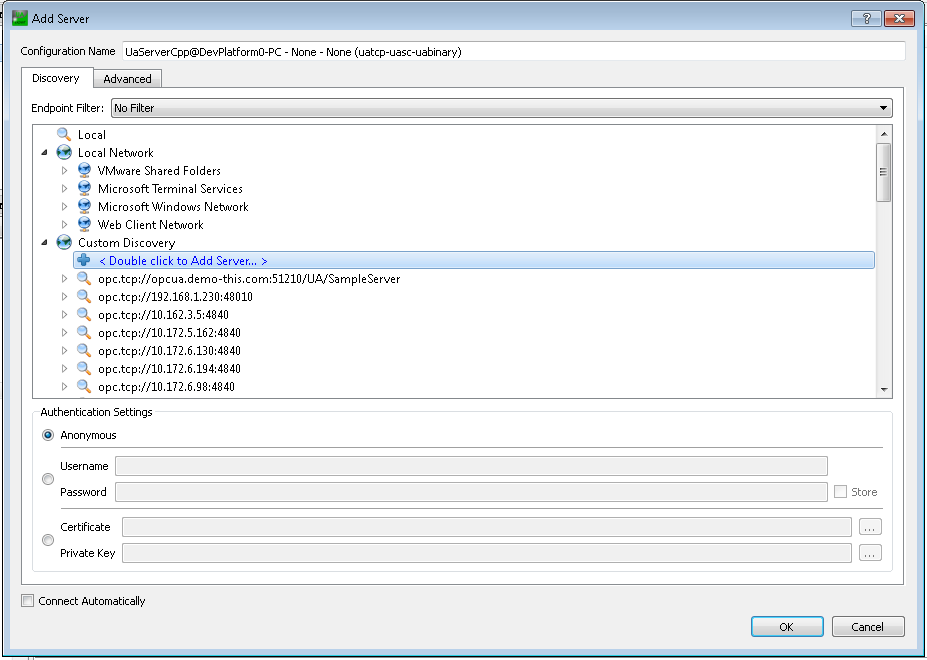
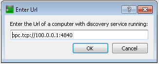
The address should typically look like this:
opc.tcp://ArgoIPaddress:4840
where ArgoIPaddress is the Argo IP address of your OPC UA device (also called a server in the context of OPC UA).
Click here to learn more about Argo IPs.
4840 is the most commonly used port for OPC UA, although this may vary.
In UA Expert, added servers will display in a list with a magnifying glass on the left, followed by the server IP address. Newest added servers will display at the bottom of the list.
Click on the triangle symbol ![]() next to the server name on the list to expand the connection selection menu.
next to the server name on the list to expand the connection selection menu.
If no dropdown appears under the server that means either the device is offline or OPC UA is not running on the device.
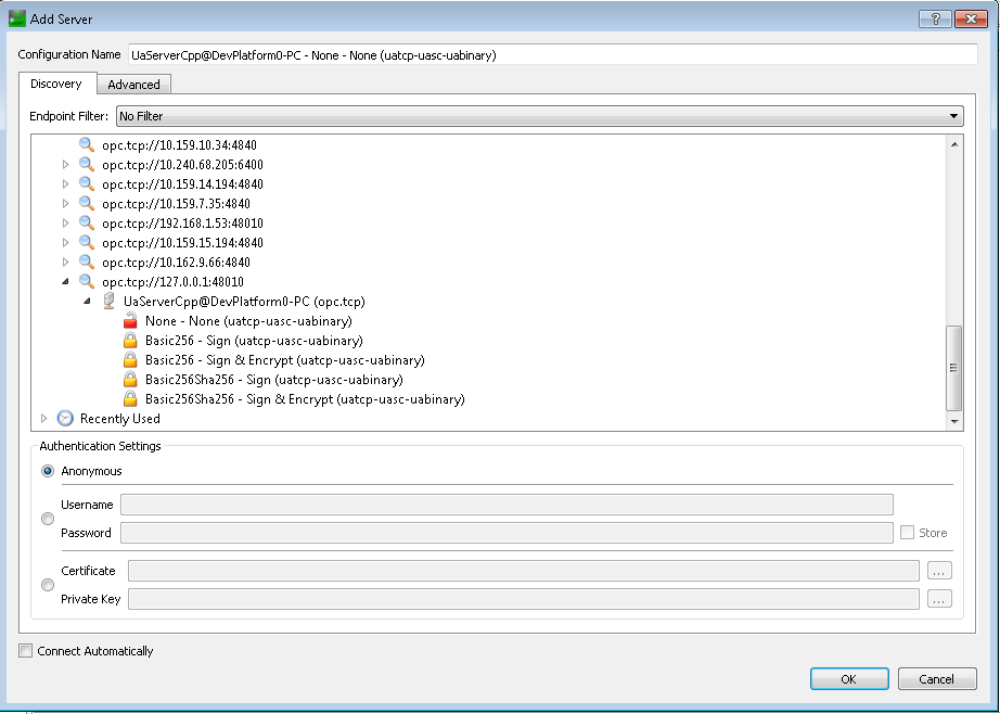
You should usually select none for the certificate – most servers will not have one to use. Double click on none and now you should have a server available that represents the device you’re trying to configure.
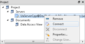
Right-click and press Connect:
Authentication Methods
Red box Amphions support several authentication methods when connecting to devices that act as OPC UA servers. For example, anonymous, username + password, and certificate-based authentication is supported.
When receiving information from the OPC UA server, the Amphion will obtain, validate, store, and use the certificate provided by the server.
When sending information to the OPC UA server, the Amphion automatically creates a certificate for communications whenever an OPC UA-enabled device is present. This certificate has a the 20-year expiration period from the date it was created. It uses the SHA-256 algorithm with 2048-bits encryption. If the certificate is deleted or the Amphion is replaced, a new certificate will be automatically issued; this will restart the 20-year expiration period.
In some cases, communication with a device won’t be possible until an authorized user accepts the Amphion-generated certificate on the device explicitly. In such cases, please contact ei3’s CARE team at care@ei3.com to request a copy of the certificate.
Finding Data Points
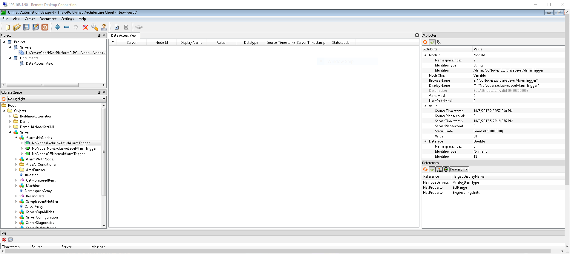
The Address Space field should update accordingly to display the server folders.
In the bottom-left Address Space section, different types of data groupings will be shown. Expand appropriate folders accordingly to see their contents, or display tags.
A selected item from these objects will display its details on the right-hand side in the Attributes section:
Finding Read Addresses
You must verify the precise accuracy of the read address for each data point. Typically the data point information will include data point name,read address, data type, and a description.
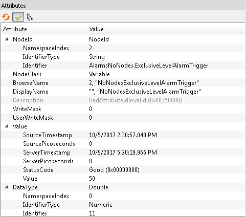
For creating data points in ei3, you will need the attribute values for DataType and Identifier.
Use the Identifier from the displayed attributes for the Read Address of the data point.
Below is a list of OPC UA data types supported by Amphion data collection.
- OPC UA
- Platform Boolean
- Boolean Byte
- Char Double
- Double Float Int16
- Short Int32
- Long Float
- Float String
- String
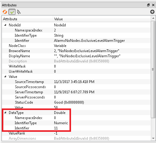
The Data Type is listed in the corresponding area shown above (in Attributes).
You can find a full list of devices compatible with each data collection type in this linked article.
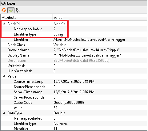
When creating data points, you must use the following format to generate a read address:NS[NamespaceIndex] |[IdentifierType]| [Identifier]
The end result would look something like this:NS2|String|AlarmsNoNodes.ExclusiveLevelAlarmTrigger
Handling Arrays
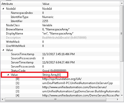
When defining data points to read elements of an array, you’ll need to find the exact string array value for that data point. The highlighted area in the screenshot shown above displays where the string array value is located.
When choosing data types during the configuration set-up process, make sure to select String as a data type. A sample read address format is displayed below:ns0|numeric|255[0]
Setting The Device Manufacturer – Category
The device which the data points will be read from must be configured with the following value in the “Manufacturer – Category” dropdown on the Edit Devices page in Customer Portal > Tools (⚙️) > Admin > Devices: “Generic – OPCUA (Amphion)”.
Adding Data Points in ei3
Next, data points must be entered into the Data Points page (found under Admin > Data Points in the Customer Portal).
Click the ![]() icon to open the new data point creation page.
icon to open the new data point creation page.
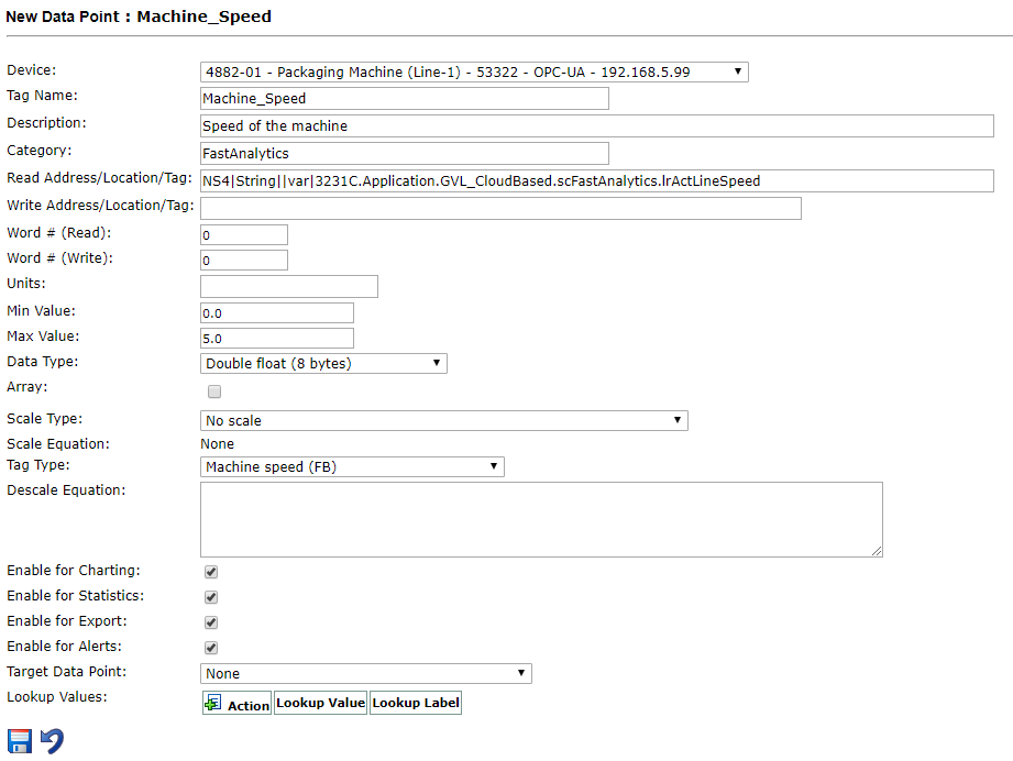
- Device: The device from which this point will be collected. NOTE: this device must have the required type in ei3: “Generic – OPCUA (Amphion)”.
- Tag Name: Name of data point. Examples include: BadProductCount, DowntimeCode, Machine_Speed, MotorTemp_AxisA1.
NOTE: the tag name may not have any spaces or special characters. - Description: Relevant description of the data point; it may include spaces.
- Category: Each datapoint falls under a category. Examples include: Temperature, Pressure, Production. These will vary according to the machine type and the manufacturer.
- Read Address/Location/Tag: This field uses many important variables, including NamespaceIndex, IdentifierType, and Identifier. In our example above, the Read Address was
NS2|String|AlarmsNoNodes.ExclusiveLevelAlarmTriggerIMPORTANT: When entering data points, the Read Address parameter is very important! This value must be precisely identical to the address found in UA Expert in order for data to be collected. - Word # (Read)/Word # (Write): In most cases this value should be zero.
- Units: Enter the units of data point values, if applicable.
- Min/Max Value: Data point’s minimum & maximum values, if applicable; they will be used for displays and charts in ei3.
- Data Type: The data type (Boolean, short, long, etc).
- Array: Check if appropriate.
- Scale Type & Scale Equation: Allows choosing of the type of the scale equation to be used for the data point. Pick a Scale Type and enter the scale equation in the text box(es) provided.
- Enable for Charting/Statistics/Export/Alerts: Allows the data point to be enabled or disabled for any of the listed purposes.
- Target Data Point: Select a data point target (if necessary).
Once the data point has been configured and all necessary fields have been entered correctly, click the Save icon ![]() at the bottom of the page.
at the bottom of the page.
After all the data points have been entered and the machine has been fully configured, you can start data collection.
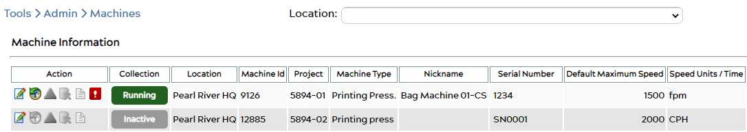
Starting Data Collection
In the Customer Portal, under Tools (⚙️) > Admin > Machines, click the button under the Collection column to initiate data collection.
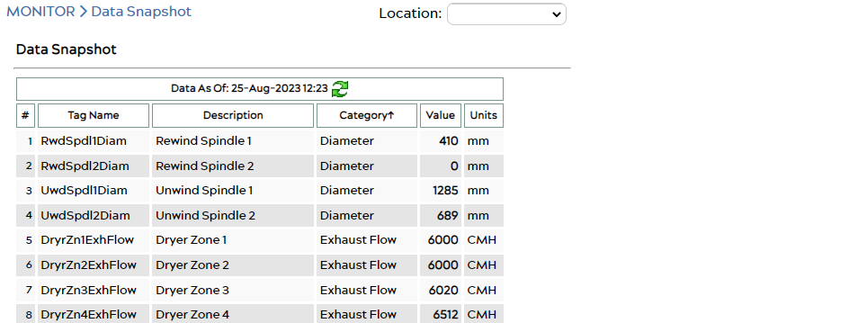
To confirm that data is being collected, wait ~5 minutes then check the MONITOR > Data Snapshot page in the Customer Portal. Your data should be displayed there with a timestamp within the last minute.