Note: LIFECYCLE can only be used on machines that have the LIFECYCLE product active.
For general information and definitions on tools please see this article: Tools – LIFECYCLE.
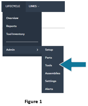
In the dashboard, first start up the LIFECYCLE app, then select Admin > Tools:
After selecting Tools, a screen like the one below will appear:
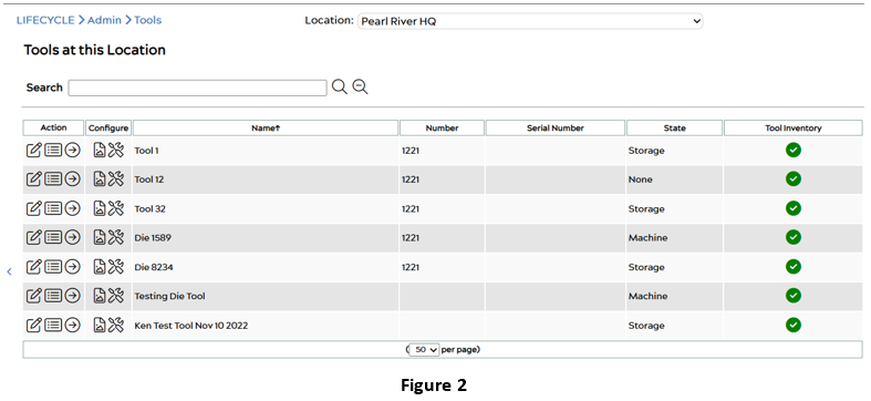 As illustrated in Figure 2, this specific machine currently has seven tools. The edit
 ![]() icon allows the user to edit the tool information. Clicking on this icon will take you to a page similar to Figure 3 (referenced below):
icon allows the user to edit the tool information. Clicking on this icon will take you to a page similar to Figure 3 (referenced below):
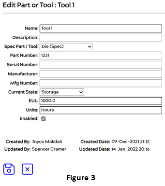
Users can edit or add any information necessary for the tool. Once done click on the save icon. ![]()
To exit the Edit Part or Tool page and return to the Tools at this Location page, select the ![]() icon.
icon.
_____________________________________________________________________________________________
_____________________________________________________________________________________________
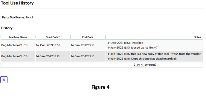
The second icon ![]() in the Figure 2 Tools at this Location page, reveals the Tool Use History of the selected tool. It indicates the start date of when the assembly was added, the end date, and any notes corresponding to it:
in the Figure 2 Tools at this Location page, reveals the Tool Use History of the selected tool. It indicates the start date of when the assembly was added, the end date, and any notes corresponding to it:
The ![]() icon in the Figure 2 Tools at this Location page is the Info icon, which brings the user to a new page as seen in Figure 5 (referenced below). This page shows the user the details of the tool including its predictions, maintenance items, and episode history.
icon in the Figure 2 Tools at this Location page is the Info icon, which brings the user to a new page as seen in Figure 5 (referenced below). This page shows the user the details of the tool including its predictions, maintenance items, and episode history.
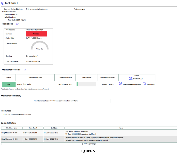
This page can also be viewed from the Overview section under LIFECYCLE on the right column. For steps on how to get to the Info page for the tool see this article: Tools – LIFECYCLE
_____________________________________________________________________________________________
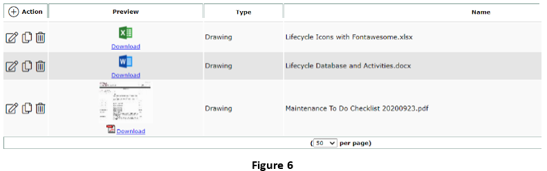
The Resources icon ![]() under the Configure column of the Tools at this Location page in Figure 2, brings users to the Resources page, which shows all the resources associated with that tool. This could include images, word documents, excel files, etc. If the user wants to add important files associated with a specific tool, they can do so using this page, and access these files at any time. An example of the resources page is shown in Figure 6 below.
under the Configure column of the Tools at this Location page in Figure 2, brings users to the Resources page, which shows all the resources associated with that tool. This could include images, word documents, excel files, etc. If the user wants to add important files associated with a specific tool, they can do so using this page, and access these files at any time. An example of the resources page is shown in Figure 6 below.
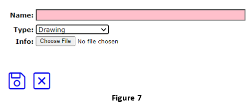
The user can add new resources by clicking on the ![]() icon next to Action. From there the user can upload a file and save it, as seen in Figure 7 (referenced below). Make sure to choose a name that best describes the resource and the correct Type of information associated with the file. Once done click on save
icon next to Action. From there the user can upload a file and save it, as seen in Figure 7 (referenced below). Make sure to choose a name that best describes the resource and the correct Type of information associated with the file. Once done click on save ![]() .
.
![]() Editing,
Editing, ![]() copying, and
copying, and ![]() deleting existing resources can also be done after they are added to this section.
deleting existing resources can also be done after they are added to this section.
_____________________________________________________________________________________________
The Maintenance Items ![]() icon under the Configuration column of the Tools at this Location page in Figure 2 takes users to a page resembling the following:
icon under the Configuration column of the Tools at this Location page in Figure 2 takes users to a page resembling the following:
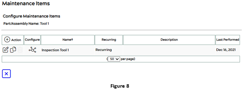
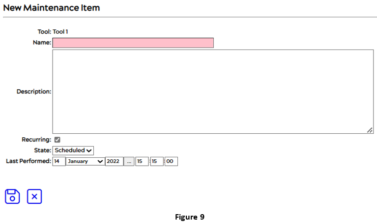
The user can add, edit, or remove maintenance items associated with a specific tool. To add a new item, select the ![]() icon next to Action which brings you to the New Maintenance Items page (Figure 9) Fill out the necessary information and then save.
icon next to Action which brings you to the New Maintenance Items page (Figure 9) Fill out the necessary information and then save.![]()
The user can also edit an existing Action by selecting the ![]() icon as seen in Figure 8’s Maintenance Items window. This will bring you to a page like Figure 10 below:
icon as seen in Figure 8’s Maintenance Items window. This will bring you to a page like Figure 10 below:
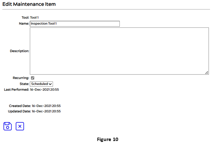
After filling in all fields, the user can save this information by clicking save. ![]()
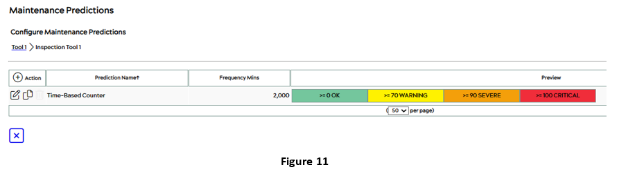 Under the Configure column of the Maintenance Items window in Figure 8, the user can select the Maintenance Predictions
 ![]() icon. After clicking on that button, the Maintenance Predictions page will appear, like Figure 11 below:
icon. After clicking on that button, the Maintenance Predictions page will appear, like Figure 11 below:
This Maintenance Predictions page displays the types of predictions within the item and the details associated with them. To view the details of the prediction for the current example click on the edit icon ![]() and a page like Figure 12 (referenced below) will appear:
and a page like Figure 12 (referenced below) will appear:
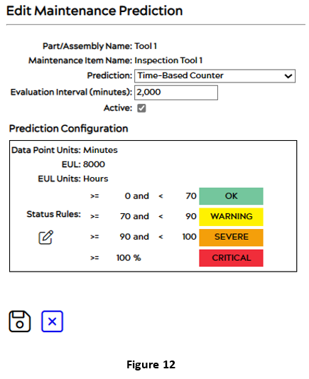
The Prediction Configuration can be changed and edited by the user by clicking on the edit ![]() icon. That way all the information can be changed or edited including the EUL, the units, and the status rules, to meet the users’ specifications. Click save once done.
icon. That way all the information can be changed or edited including the EUL, the units, and the status rules, to meet the users’ specifications. Click save once done. ![]()
To add a new maintenance prediction, click on the ![]() icon next to the Action column as seen in Figure 11. After selecting that button, a page like the following Figure 13 will appear:
icon next to the Action column as seen in Figure 11. After selecting that button, a page like the following Figure 13 will appear:
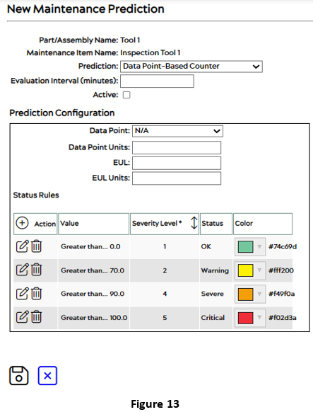
After filling out this page, click save to save all edits. ![]()
For more information about predictions and maintenance items please see this article: Tools – LIFECYCLE
